1.0 A pre-cursor: review Humidity Variables
An appendix to these web notes covers the humidity variables: vapour pressure (partial pressure of water vapour) e, absolute humidity (vapour density) ρv, and specific humidity q=ρv/ρ where ρ is the air density. You may recall that the ideal gas law for water vapour reads
e = ρv Rv T
where e is in [Pa = N m-2], ρv is in [kg m-3], T is in [K] and the specific gas constant for water vapour Rv = 462 [J kg-1 K-1].
Saturation (equilibrium) Vapour Pressure
Imagine a small volume of water at rest in a larger, closed, isothermal (temperature, T) container, which is in equilibrium with a heat bath at (necessarily, the same) temperature T. The molecules of liquid water are in random thermal motion, and individuals are continually escaping from the liquid surface. Even if initially (time t=0) there were no vapour molecules in the container, at t>0 there will be, due to these escaping liquid molecules. More and more molecules will escape from the liquid and build up the vapour pressure, until an EQUILIBRIUM is reached, in which there is a sufficient number of vapour molecules than the frequency of re-entry into the liquid equals the frequency of escape. The vapour pressure at this equilibrium point is called the "equilibrium vapour pressure" or "saturation vapour pressure," and is a function of temperature T, symbolised as e*(T) or es(T).
If vapour pressure e is known you can infer Td, and vice versa, using a saturation vapour pressure table. (Table of es(T) versus T and other properties of air).
2. Wet- and dry-bulb Psychrometer
Consider the energy balance of the Wet-bulb Thermometer. Assuming a steady state, ie. that air temperature (T) and wet-bulb temperature (Tw) are not changing, the energy balance may be expressed:
0 = A ( Q* + QH + QE)
where A is the surface area of the thermometer and QH, QE are the sensible and latent heat flux densities, for which we have earlier developed mathematical models (based on the Ohm's Law analogy). If we assume that radiative energy exchange (Q*) can be ignored, ie. that the thermometers are adequately radiation-shielded and ventilated, then we can simplify:
0 = ρ cp (T-Tw)/rH + (ρ cp/ γ) (ea-ew)/rV
Now further assume that rH=rV (which is a fairly good approximation), so that the common factor ρ cp /rH cancels from the equation. Also, we can note that since the air in contact with the wet-bulb is saturated, ew=e*(Tw). So we can re-write our equation as:
e = e*(Tw) - γ (T - Tw)
This is the equation of calibration for a wet-bulb thermometer, derived from first principles.
Pitfalls in the use of a wet- and dry-bulb psychrometer:
γ = p cp / ( 0.622 L )
where L [J kg-1] is the latent heat of vaporization evaluated at temperature Tw.
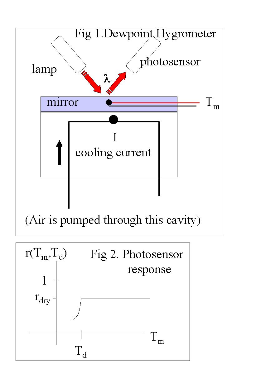
3. Dew-point Hygrometer
A stream of air is pumped through a cavity where it blows across a mirror ( Figure 1: Cooled-Mirror Dewpoint Hygrometer). The mirror surface- temperature Tm is manipulated by a thermoelectric heater/cooler (increasing cooling current I increases the rate of cooling of the mirror), and is monitored by a thermistor or thermocouple. The mirror is cooled to the dewpoint, so that condensation on the mirror occurs. If the mirror surface is hydrophobic, water deposits as droplets rather than as a film, and the result is that the mirror reflectivity (r <= 1) is reduced from its "dry" value (rdry). A photodetector (here we assume its a photo-resistor) measuring the light reflected off the mirror from a source, detects the change in reflectivity.
The previous figure showed schematically the variation of the reflectivity with mirror temperature. In operation, a feedback loop keeps the mirror temperature constant at a value which keeps the reflectivity constant (or exhibiting minute variations about) a value slightly below the dry value,
rop = rdry - dr.
In other words, the mirror temperature is controlled at (or very close to) the dewpoint by using a feedback circuit that maintains a Wheatstone Bridge in balance. Control will be achieved provided that, in the region of the operating point (ie. when Tm is close to Td), any increase(decrease) in mirror temperature causes the resulting error voltage (V) to result in an increase (decrease) in cooling current. Thus, we need dI / dTm > 0
Now, the chain rule of Calculus lets us express this as the requirement that:
dI / dTm = G dV / dTm = G dV/dR dR/dr dr/dTm >0
It is easy to show using our voltage-divider rule that if the photoresistor resistance R increases, V decreases, ie. we can prove that dV/dR < 0. Proof: The error signal (bridge imbalance) is given by:
V = VB [ R3 / (R3 + R(r)) -R2 / (Rc + R2)].
By differentiating, you can show that dV/dR < 0.
We saw above that near the operating point dr/dTm >0, ie. if the mirror temperature increases we get increased reflectivity. What about the sign of dR/dr? This depends on the specific sensor element... suppose the photosensor resistance is given by
R = Ro [ 1 + ln (1/r) ]
Then around the control point, as r increases, R decreases, and so Rop = Rdry + dR, and dR/dr <0. Our control circuit is stable - provides the required feedback to correct any bridge imbalance. If Tm increases away from the control point, the error signal increases, increasing the cooling current.
Now, to keep the reflectivity constant, we need a constant equilibrium water load on the mirror. Thus, the operating point (the equilibrium) can only occur at the dewpoint temperature of the air, Tmbalance = Td.
The dewpoint hygrometer is an absolute device (ie. provided the mirror temperature is suitably controlled, dewpoint calibration goes back to the calibration of the thermometer measuring Tm). Of course there are small uncertainties relating to the difference between the temperature at the sensor, and true surface temperature. Careful operation of such a device can yield an accuracy of order ∼ 0.5oC in dewpoint. The response time of the dewpoint hygrometer is long (minutes), and so it is not suitable for rapid measurements.
4. Lyman-α Humidiometer
This humidiometer is a special case of the "Electromagnetic Absorption Gas Analyser."
Lyman-α radiation is E/M radiation due to electronic state-transitions in hydrogen atoms. Lyman-α photons have wavelength in the ultraviolet, λ=121.56 nanometers. Water-vapour molecules absorb Ly-α photons. Thus by monitoring the fluctuations in the intensity of a Ly-α beam passing through air, one can sense the absolute humidity.
The detector current is
I = Io exp [- k d ρv ]
where Io is the "dry" current, d is the pathlength through air, ρv is the absolute humidity, and k (a constant) is the absorption coefficient of Ly-α radiation in water vapour. Differentiating, you can show that
d ln(I)/ dρv = - k d
so that we have a linear variation of ln(I) with ρv about some operating point.
This device is small and fast (ideal for eddy correlation). However it is expensive, and the uv-lamp decays quickly. The salt windows deteriorate due to moisture.
5. Closed Path Differential Absorption Infra-red Gas Analyser
This is a very important class of gas analyser, and devices exist to measure a great range of trace gases, sensed by selection of a wavelength λ
Description of the LI-6262 Differential Infra-Red Gas-Analyser :
The Li-Cor LI-6262 is a differential infrared gas analyser for measuring concentrations of CO2 and H2O. A beam of infrared-radiation is passed through each of two gas chambers. One chamber is the "reference cell," and when the Li-Cor is used in "absolute mode," the reference cell should contain zero concentration of CO2 and H2O. The other chamber is the "sample cell," through which a stream of air is pumped down a tube from the sampling-intake. The measurement is based on the greater degree of IR absorption in the sample cell than in the reference cell.
The IR radiation source is a heated sphere, held at 1250 K. IR radiation from the source is collimated and the resulting beam is sent along through the two cells, at the end of which the beam is re-focused and directed toward two separate detectors for CO2 and H2O. The IR radiation is passed to each detector through an optical filter (width of the radiation pass-band is about 150 nm, ie. 0.15 μm). The optical pass-band for the CO2 detector is centred on a λ =4.26 μm CO2 absorption band, while for the H2O detector, a λ=2.59 μm absorption band is selected.
The CO2 and H2O measurements are based on the difference in absorption of ir radiation in the sample and reference cells. The output voltages are V = k ( vs - vr ) where vs is the (CO2 or H2O) detector signal when seeing the sample cell, and vr the (corresponding) detector signal when seeing the reference cell. The ratio vs/vr is just the "transmittance," which in turn is simply 1-A, where A is the "absorptance." It follows that output voltage V = m A, where m is a constant. The absorptance, and thus output voltage, is a non-linear function of the gas concentration.
Performance Specifications: CO2 and H2O noise levels are of order 1 [ppm] and 0.01 [kPa] (ie. 0.1 [mb]) when the analyser is working with an airstream having CO2 concentration of about 350 [ppm] and vapour pressure (e) of about 2000 [Pa].
Back to the Earth & Atmospheric Sciences home page.